Instrument step parameters
Each step of a method/analysis appears in the Chromatography tab and can be configured by clicking on it. The Plate Layout step always appears first Though each instrument has its own set of parameters, they share common behaviors:
Default values are given to the different parameters in order to simplify the configuration for the user, meaning that you often won’t have to configure manually each step.
Tnstrument configuration windows have been designed to present the most important parameters first and to allow the user to access advanced parameters if needed (easy/expert paradigm).
Each instrument step has a Notes field and classic OK/Cancel buttons.
You can navigate back/forward through the analysis steps by using the corresponding buttons in the header of the step tooltips.
Here is the list of the different steps available:
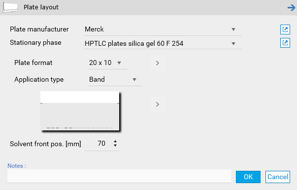
Plate Layout
Define here the global parameters relative to the plate to be used and to the application.
Note
Be careful to configure the plate format according to the CAMAG instruments in use.
Note
When switching from/to Left/Center in the Track Assignment, the First track position X parameter is set.
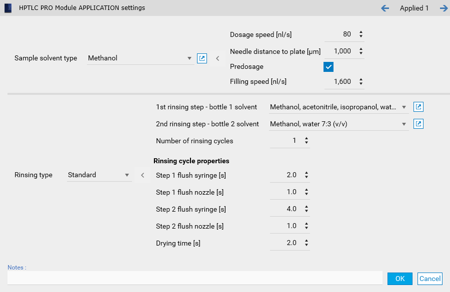
HPTLC PRO APPLICATION
Define here the parameters relative to the execution of the HPTLC PRO Module APPLICATION.
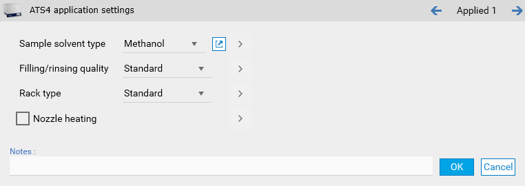
ATS 4
Define here the parameters relative to the execution of the ATS 4 instrument. The window provides default solvent types and filling/rinsing quality configurations.
Note
Rack positions are defined in the Track Assignment
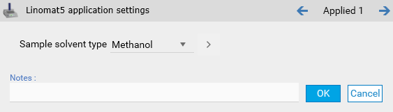
Linomat 5
Define here the parameters relative to the execution of the Linomat 5 instrument (semi-automatic application).
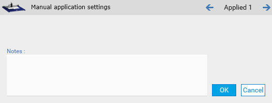
Manual application
Manual application step with any kind of manual application device:
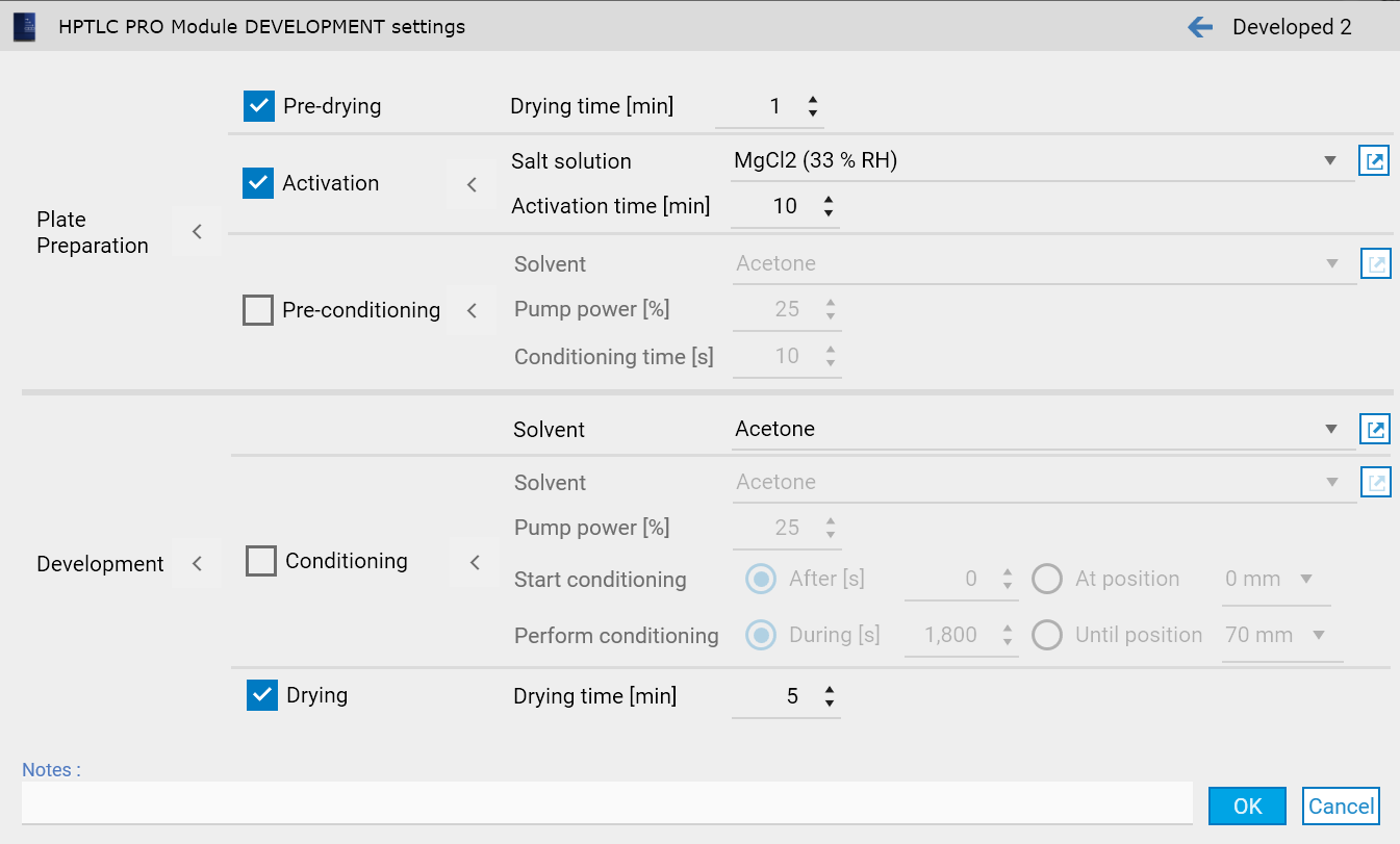
HPTLC PRO DEVELOPMENT
Define here the parameters relative to the execution of the HPTLC PRO Module DEVELOPMENT (single application).
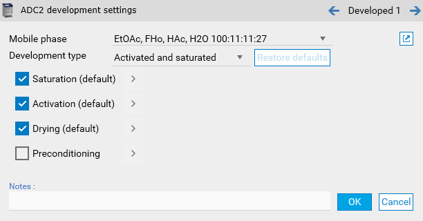
ADC 2
Define here the parameters relative to the execution of the ADC 2 instrument (single application). The window provides some default development type parameters.
Note
When having several ADC 2 steps, the solvent front position can be defined here and not only in the Plate Layout parameters.
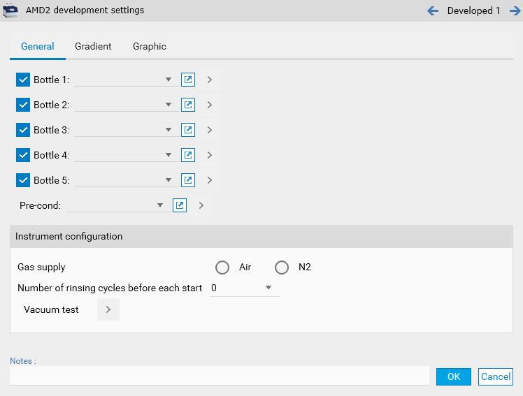
AMD 2
Define here the parameters relative to the execution of the AMD 2 instrument (multiple applications). The General tab handles the configuration of the bottles and the instrument itself.
The Gradients tab contains the configuration of the gradients steps, with auto-fill options.
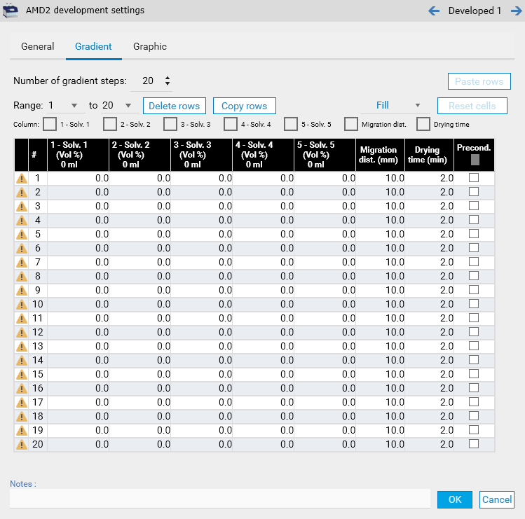
Note
The Graphic tab consists in a visual representation of the Gradients tab.
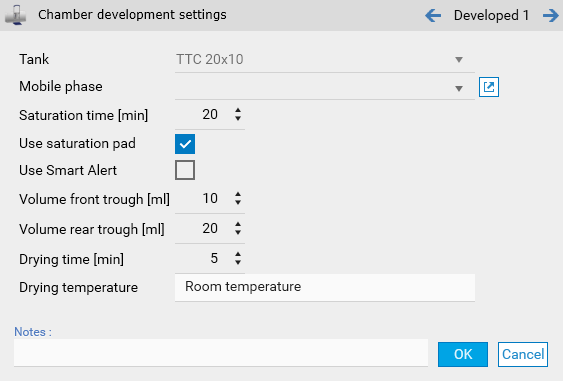
Chamber
Define here the parameters relative to the execution of a development in a glass development chamber.
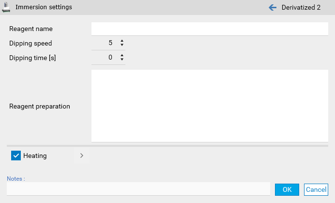
Immersion
Define here the parameters relative to the execution of a derivatization by dipping.
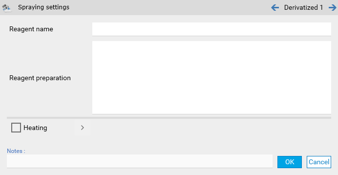
Spraying
Define here the parameters relative to the execution of a derivatization by spraying.
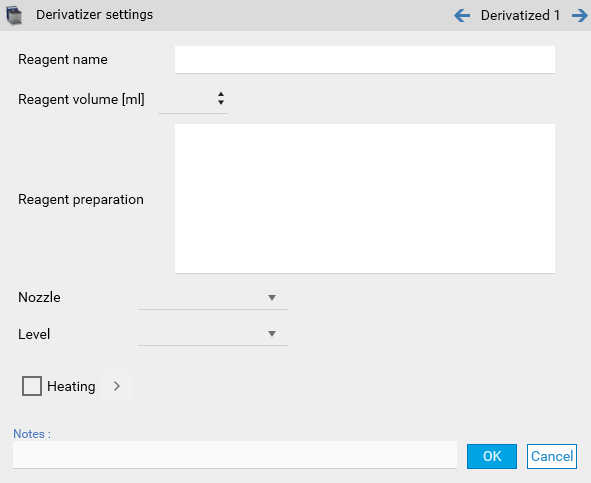
Derivatizer
Define here the parameters relative to the execution of the Derivatizer instrument.
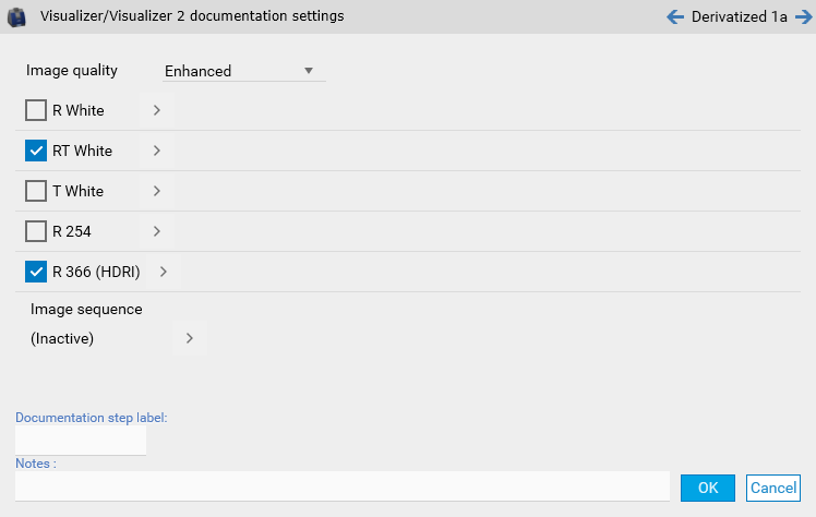
TLC Visualizer/TLC Visualizer 2
Define here the parameters relative to the execution of a TLC Visualizer/TLC Visualizer 2 documentation step. A visualizer step can contain up to 5 images (called Illuminations), with the possibility to repeat them in a sequence.
Note
The Documentation step label field can facilitate the identification of documentation step data when using them.
Note
The Visualizer High-Res documentation package option is required to take Enhanced images.
TLC Scanner 4
Define here the parameters relative to the execution of a Scanner 4 documentation step.
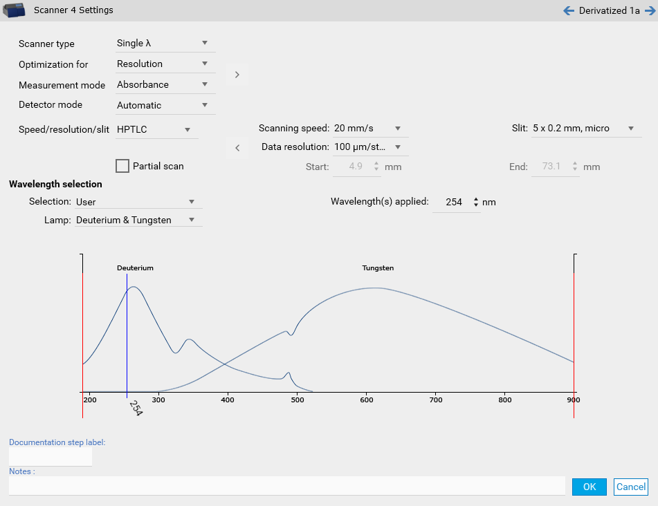
A scanner step can be used to perform a single-wavelength, multi-wavelength or spectrum measurement. When choosing multi-wavelength, it’s possible to define a pattern to apply:
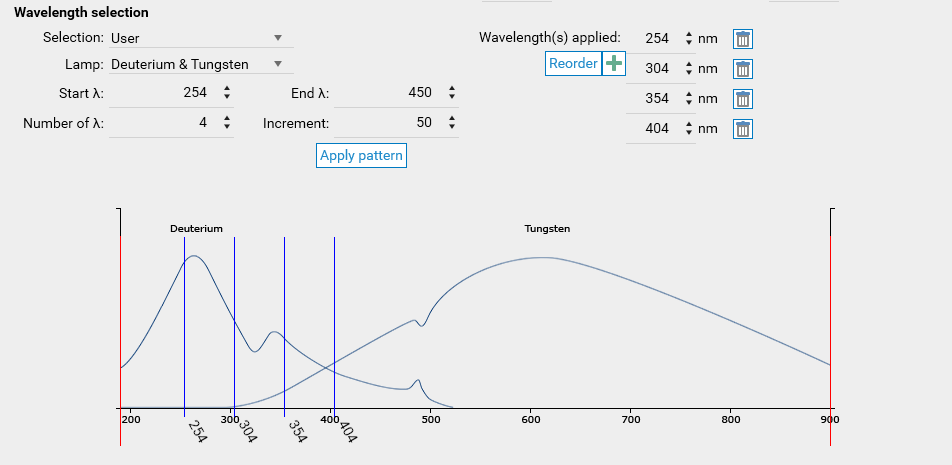
Note
An Advanced mode is also available, where the measurement mode, lamp and filter can be set independently for each wavelength.
When choosing spectrum, the range and some specific parameters have to be set:
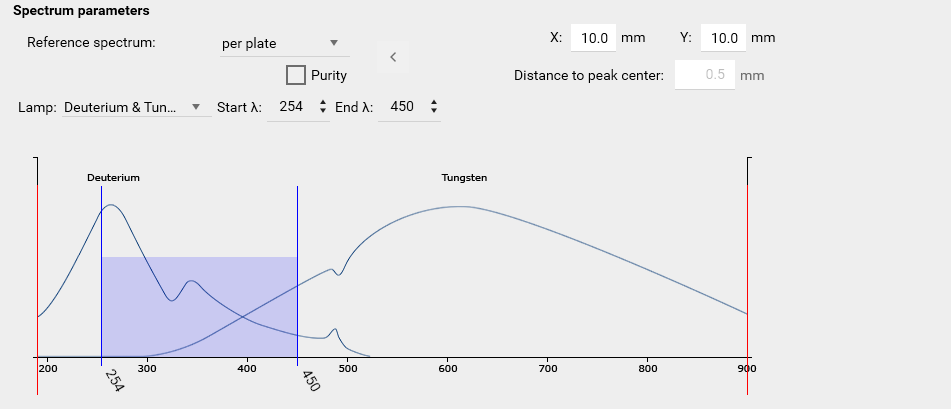
Note
The Documentation step label field can facilitate the identification of documentation step data when using them.
Note
The Multi Wavelength Scanning option is required to use the multi-wavelength mode.
Note
The Spectrum Scanning option is required to use the spectrum mode.
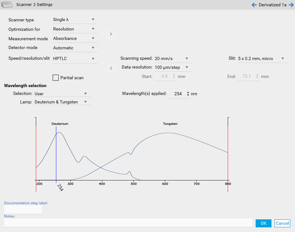
TLC Scanner 3
Define here the parameters relative to the execution of a Scanner 3 documentation step. The parameters are the same as the ones used for a Scanner 4 step, except that the maximum wavelength for a Scanner 3 step is 800 nm instead of 900 nm.